

With electronics moving more into high-frequency operations, it is imperative that various devices operate without disturbing others operating nearby. When electric current flows in a closed circuit, it generates magnetic fields that can interact with other magnetic fields nearby. The capability of electronic circuits operating without disturbing or disrupting other operations is called its electromagnetic compatibility. Rush PCB Inc recommends using good practices by designers when laying out printed circuit boards that help in improving electromagnetic compatibility.
PCBs and Electromagnetic Interference/Compatibility
All electronic circuits allow flow of electrons for accomplishing some performance objective. The flow of current or electrons through closed paths creates magnetic fields projecting outward and perpendicular to the flow of the current. Electromagnetic interference occurs when there are nearby signal paths or other electronic elements.
For PCB assemblies, especially those operating with high-speed signals, it is a primary consideration to control and manage the amount of EMI the board generates. In boards that use components known to be radiators, it is imperative to implement EMI filters and shields. Although filters can be effective, using good practices in PCB design that reduce EMI is recommended.
Difference Between EMI and EMC
Most systems contain more than one PCB assemblies operating near each other. Not only do individual components, conductors, or traces generate electromagnetic energy, the board also radiates it into the environment. When multiple boards are operating in proximity, the electromagnetic energy from one can easily influence the operation of others. If a board is capable of disturbing others nearby, it is a generator of electromagnetic interference or EMI. If a board is susceptible to disturbance from those operating nearby, it has a problem of electromagnetic compatibility or EMC. A good PCB designer must follow good practices that aim to curb both EMI and EMC.
The Importance of the Return Path
Designers must reference all high-speed signals on a PCB to a solid plane. A current flowing through a trace on a PCB typically travels the entire circuit loop to come back to the source. The return current always takes the path of least impedance. As it returns via the solid plane, it forms the smallest loop compared with the incident current path. This not only minimizes the loop inductance, but also helps cancel the magnetic field generated by the incident current.
Potential EMI/EMC issues typically originate when there is no correct account of the signal return. Good design guidelines always reference the signal for a proper return path. The following rules check for potential issues of EMI/EMC generation in PCB design.
Return Path through Layers
It is possible for a high-speed signal trace to travel through multiple layers in a PCB. It traverses these layers through vias that interconnect the layers. However, for designers, it is easy to forget assigning the path of the return current when it has to traverse two or more layers.
For instance, a high-speed signal traversing a trace in the top layer may reference a plane closer to the top layer. However, as the trace goes to the bottom layer through a via, it may have to reference to another plane closer to the bottom layer. As the return path is now inconsistent, it can lead to EMI/EMC issues because of unwanted radiation in the via region.
The designer must avoid such changes in reference. If the change is unavoidable, the designer must connect the two planes using stitching capacitors or vias. Placing the vias and/or capacitors as close as possible to the region where the signal is transitioning, allows the return current to take the smallest possible loop.
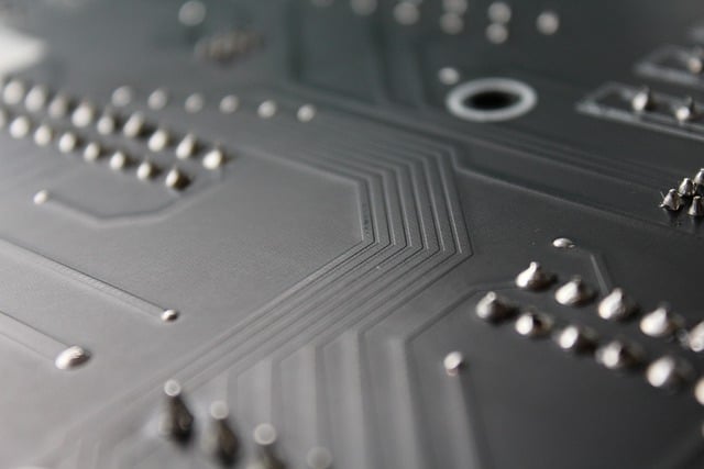
Traces close to the Edge of the Reference Plane
As long as the trace carrying high-speed signals is well within the reference plane, the electric field properly couples to the reference plane, and any magnetic field remains within the PCB. However, for traces routed close to the edge of the reference plane, it can no longer contain the electric lines totally. This allows the magnetic lines to leak outside the intended PCB plane.
These leaked magnetic and electric fields can couple to other traces nearby or on to adjacent boards nearby. They may also couple to existing cables nearby in the system. This can lead to unintended radiation and emission issues.
Split in the Reference Plane
Sometimes, PCB designers may have to split a reference plane. If this is a reference plane associated with a trace carrying high-speed signals, the return current may be forced to go around the split. As it takes a longer path, it results in a higher loop inductance, leading to potential EMI/EMC issues.
While a split in a reference plane is not advisable, in some cases it may be unavoidable. The designer must counter this by placing a stitching capacitor across the split to provide the high frequency return path, such that there is not much of a deviation across the split. It is advisable to place these capacitors as close as possible to where the track crosses the split plane.
Unbalanced Differential Pair Routing
A trace carrying high-speed signals can generate EMI along its path or at connectors pinpoints. For instance, if the differential pair routing remains unbalanced, it may cause signal reflection and attenuation along the track, thereby severely affecting signal integrity and resulting in erroneous circuit behavior. Moreover, stray capacitance may cause unwanted coupling between signal path and ground plane, resulting in unwanted EMI.
PCB Layout to Minimize EMI Generation
Proper spacing is very important to minimize EMI. This includes maintaining recommended clearance and creepage distances between elements.
- Signal traces must employ adequate clearance in between
- Properly ground all grounding and bypass capacitors
- Place ground capacitors as close to component pins as possible, to avoid generation of stray capacitance
- Minimize the length of return paths
- Make ground returns as short as possible
- Make differential traces as identical as possible—trace lengths, copper weights, and separation must be identical
- Avoid sharp angles in traces and planes
- Use rounded edges for bending traces
- Do not use adjacent conducting layers, separate them with a ground plane
- Use separate grounds for different signal types
- Combine split ground planes at a single point
Reducing EMI from External Sources
- Use proper shielding
- Use enclosures
Conclusion
Rush PCB Inc recommends following the above guidelines for PCB components, layouts, and external sources to minimize the effects of electromagnetic interference and improve the electromagnetic compatibility for a PCB assembly. However, some changes may be necessary to accommodate the design requirements, functionality, and performance objectives of the assembly. Additionally, we also recommend use of computer analysis tools for optimizing your design for EMI/EMC.


