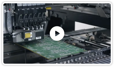
Ensuring Reliable PCB Assembly: Challenges and Importance
With PCBs becoming increasingly complex, not only has the number of layers increased, but so have their manufacturing processes, and the importance of PCB assembly reliability. Although a single PCB assembly can have tens of thousands of soldered joints, just one faulty joint can cause an entire board failure. Even minor failures can affect the performance of a product in the field, risking warranty issues, recalls, extended design revisions, and more.
While functionality tests may be adequate to demonstrate overall board performance, they alone may not be sufficient to understand the wear and tear on the PCB assembly during use or when it is exposed to environmental factors. There may also be errors in process design, wave-soldering, or reflow-soldering, and these could result in product failure.
Building Quality into the PCBA
To prevent defects in PCBA, we, as manufacturers, build quality in early in the design phase, thereby mitigating the quality, reliability, and thermal issues that could impact performance.
Below, we have explored selected technical insights, including common failures, challenges, and best practices, from Rush PCB Inc.’s work with PCBAs.
Component-Level Considerations
- Insufficient consideration of structural and process designs, leading to excessive loads and failure, is a common vulnerability of PCBA components. For instance, thin-film ceramic resistors and multilayer ceramic capacitors are extremely fragile and are vulnerable to assembly stresses that soldering may cause.
- Care must also be taken when reworking the PCBA, for instance, when repairing or modifying it. Heating the solder joint to remove a PTH component during repair can potentially damage the joint, specifically between the annular ring and the barrel.
- With lead-free solder, soldering temperatures are critical. Tighter temperature settings are necessary because lead-free solder has a higher melting temperature. The operator needs to set the process temperature properly to ensure good bonding without damaging components, or the high temperature may damage the components and even the board.
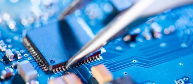
Soldering Considerations
We solder electronic components onto the PCB with solder alloy and flux, forming solder joints. During the assembly process, we perform surface mounting, PTH insertion, wave-soldering, and reflow soldering processes, with precisely controlled process parameters to mitigate possible reliability and product safety issues. There can be several failure modes related to soldering:
| Failure Mode | Cause | Remedy |
| Cold Solder | Insufficient temperature during soldering, or excessive heat causing component deformation, disallowing merging of terminals at melting temperature of solder alloy. | Thermal relief or other process-related thermal features may be necessary to enhance wettability or solderability. |
| Head-in-Pillow | A potential non-wetting problem occurs during the melting process of soldering. Occasionally seen in BGA components during reflow — although the solder ball under the BGA component is attached to the solder pad, the molten solder has not formed a complete joint. | It may be necessary to carefully select the process parameters to suit the solder paste and flux type. Reflow soldering profile is very important to set for each type of PCBA. |
| Bridging | Any unexpected contact or connection between two solder joints that should not connect electrically. | It may be necessary to conduct a pre-warpage analysis if the PCBA has large BGA components. A warpage mitigation strategy may be necessary during the initial design process. |
| Warpage | During the reflow process, expansion differences between BGA and the PCB may cause excessive deformation of solder balls. | It may be necessary to evaluate a reasonable amount of solder paste deposition during the stencil printing process. |
| Non-Wetting | Flux or molten solder fails to cover the soldering pad or terminals during reflow, preventing an effective soldering connection. | Strict quality controls may be necessary during the incoming inspection process, preventing excessive oxidation or improper storage temperatures. |
| Hot-Tearing | Excessive cooling rate or deformation in solder joints may cause bulk solder separation from the joint. | A proper design of the thermal balance and mechanical balance for the PCB may be necessary. |
| Component Damage | Excessive temperature rise during soldering. | It may be necessary to perform automated quality inspections before and after the soldering process. |
Thermal Considerations
With electronics becoming faster, smaller, and more complex, PCBAs require more power and this occasionally raises their operating temperature. Designing the PCB with an effective thermal performance is a critical factor, as more than half of all electronic components fail due to heat stress, a mismatch of CTE, or heat-induced material degradation. Some best practices we follow to address thermal considerations are:
| Thermal Considerations | Best Practices |
| Heat Generating / High Power Components | Adequate component spacing between high-power components. It may be necessary to strategically locate the components based on their operating/heating power. |
| Excessive warpage of components and PCB. | To improve thermal dissipation, it may be necessary to use a thicker copper foil in the PCB layer stacking or add thermal vias. Copper balancing for both top and bottom layer at the time of design and in between the circuitry where space allows. |
| Overloading and fatigue of components and solder joints. | It may be necessary to use PCB lamination with a lower CTE mismatch with the component. |
| Long-term degradation of material or components. | It may be necessary to perform computational simulations on the thermal behavior of the PCBA before finalizing its design. |
| Distortion due to non-uniform heating. | It may be necessary to add external features like heat sinks or fans to aid in thermal dissipation. |
Rush PCB Inc. has extensive experience in helping our customers review their design processes to improve product quality and reliability. We have multidisciplinary teams to evaluate the degradation of PCB materials, assess their impact on product lifecycle, and identify potential quality and defect issues while providing solutions and mitigation methods. We have inline AOI to detect defects. An offline X-ray machine is used to detect solder wettability and adequate solder joint.
RUSH PCB Inc is familiar with all aspects of Plated-Through-Hole technology. The engineers at RUSH PCB Inc work with you on engineering and design of your Plated-Through-Hole printed circuit.
Let our engineers assist with your design for manufacturability (DFM) issues related to PTH technology in your assemblies. Contact us at [email protected], or call us at 1-408-496-6013
FAQs
What is Reliability Testing of PCBs?
Functionality test of PCBA
- Visual inspection.
- In-circuit testing (ICT)
- Flying probe testing (FPT)
- Automated optical inspection (AOI)
- X-Ray inspection.
- Burn-in testing.
- Functional testing (FCT)
Apart from above test Reliability assessment of a PCB requires a set of tests focusing on:
- Climatic or mechanical loading — Thermal cycling, extreme temperatures, and heat flux
- Electrical loading — EMC, derating verification, and high power
- Chemical loading — chemical exposure, and corrosion
- Exposure to dust, liquids, particles
- Exposure to ionizing radiation
- Artificial aging
What is PCB Failure Analysis?
What are Some of the Most Common PCB Defects?
What Mechanical Damages Can Occur to PCBs during Manufacturing?
Can PCBs Become Contaminated during Production?