Flexible Circuit Boards Manufacturer
Rush PCB Inc makes flexible and rigid-flex printed circuit boards for the electronic industry. Flex PCBs or Flexible PCBs are special types of printed circuit boards with the ability to bend and flex. These boards are typically transparent, thin, and made of a flexible, non-conductive substrate. The non-conducting material serves to insulate and protect the copper circuits on various layers of the board, while vias and plated through holes connect them electrically.
Introduction to Flex PCBs
Besides the regular rigid printed circuit boards, many electronic devices use flexible PCBs extensively, mainly for their bending ability and flexing properties. Many industries use flex and rigid-flex PCBs including consumer electronics, aerospace, defense, medical, industrial, automotive, telecommunications, and more. As electronic equipment becomes increasingly smaller, the printed circuit board inside them must also follow suit. The advantage of flexible boards is OEMs can fit them into tight spaces within the smaller devices.
Like regular PCBs, flex PCBs can also be single-, double-, or multi-layered, and single- or double-sided. In flex boards, each circuit layer counts as an individual PCB layer. However, unlike rigid boards, flex boards are thin and flexible, ranging from 0.05 mm to 0.6 mm.
Structure and Material of Flex PCBs
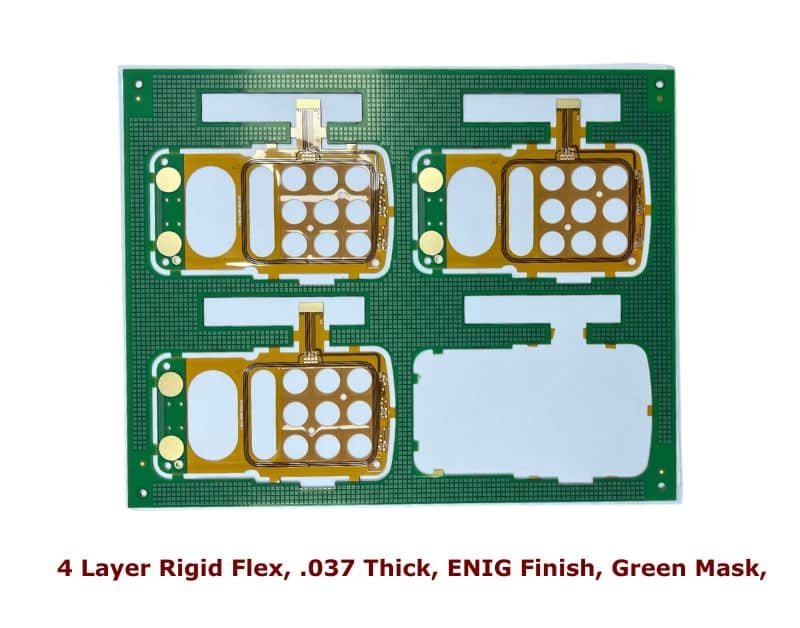
A typical four-layer flexible PCB will consist of:
Core Layer — Typically made of Polyimide (PI) material, the core of the flexible PCB is usually yellow, but it can also be transparent, white, or black. Both sides of the core will have circuits made of copper foil.
Copper Foil Layer — These foils are typically of rolled or annealed copper, adding significantly to the ductility and the ability of the board to flex repeatedly. The fabricator etches the copper foil to make the necessary circuits. Copper thickness on each layer of flex PCBs is typically 3 oz. The fabricator may use an optional adhesive layer to bond the copper foil to the core. The presence of an adhesive often makes the flex PCB less transparent, typically making it darker.
Insulating Layer — A thin PI layer insulates the copper circuit layers from the next layer above them. The PCB industry calls the two outermost insulating PI layers of a flex board cover-lays, and these are equivalent to the solder mask layer in regular PCBs.
Vias — Each copper layer can have Microvias or laser-drilled holes, and typically plated through to make them conductive. Vias are necessary to connect between copper circuits in different layers. Fabricators can stagger or stack Microvias to simulate blind and buried plated through holes typical in regular rigid boards.
Stiffeners — To allow connection of flex PCBs to connectors and other system interfaces, fabricators provide flex boards with stiffeners. They laminate rigid pieces at the end of the flex board as stiffeners. Fabricators may make these optional attachments from PI, FR4, or stainless steel, depending on the application requirement.
Manufacture of Flex PCBs
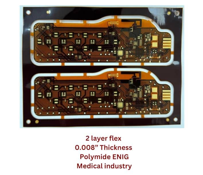
The fabricator laminates two sides of the PI core with copper foil layers. A two-layer flexible board typically consists of a PI core and two rolled copper layers on both sides. The fabricator then etches the copper layers to form the necessary circuits. They also drill Microvias and plate them to establish interlayer electrical connections. They insulate and protect the two copper layers with PI coverlays.
For multi-layer flexible PCBs, fabricators laminate alternating layers of copper and PI insulating layers on the flexible PCB core.
Design Considerations — Flex PCBs
Producing a reliable product based on a rigid-flex PCB requires attending to several considerations relating to the design of the board’s copper pattern, its fabrication, and end-use. Following these design considerations will ensure high yield and durability.
It is possible to use any stack-up with flex PCB design. However, it is necessary to consider material properties and production steps involved to avoid unnecessary expense. For instance, flexible circuits tend to build up stresses within materials as the circuit flexes and bends. Moreover, copper typically suffers work-hardening, with fatigue fractures occurring eventually with repeated flexing, leading to damage.
Use Multiple Separate Flex Circuits
Rather than use a single multi-layered flex circuit, using multiple separate single-layer flex circuits offers greater reliability. Each single-layer flex circuit will have its copper layer at the center of the median bend radius. This allows the film coverlay and substrate to flex with the greatest tension and compression.
Avoid Bends at Overlapping Sections
It is best to avoid bends at overlapping sections, especially where the length of the flexible section limits the radius of the bend. Usually, the polyimide material is elastic enough to withstand repeated flexing, but the multiple copper layers cannot withstand repeated movement.
Place Components in Rigid Section
It is preferable to have the flexible section devoid of all components. Placing all component mountings in the rigid sections allows the flex part to bend with greater reliability.
Place Copper Traces at Right Angles to the Bend
Copper traces following the bend will suffer higher flexing, with greater chances of failure. Placing them at right angles to the bend will reduce their exposure to flexing, thereby improving reliability.
Change Width Gradually
Any abrupt change in the width of a flexing section will form a weak spot, where the copper tracks will undergo fatigue over time. Mitigating this requires a gradual change in width.
Likewise, any abrupt change in width of the copper track in a flexing section will also be a weak spot. It is advisable to taper down the track as it nears a pad, or place teardrops where the track ends in a pad or a via in the flex circuit.
Use Hexagonal Hatched Polygons
Rather than use solid or normal hatched polygons for power or ground planes, it is advisable to use hexagonal hatched polygons. The hexagonal pattern reduces stresses on the hatched traces as the board flexes.
Advancements in Flex PCBs
New product designs are driving advanced requirements in the fabrication and assembly of flex and rigid-flex circuit boards. This is leading to the use of newer circuit board materials, stack-ups, and constructions that allow a wide variety of advanced configurations.
The above options, in turn, are creating significant opportunities for achieving higher levels in packaging density and design integration within specific designs.
Future of Flex PCBs
Manufacturers are creating many new designs with substantially larger flex layer counts. More prevailing designs are including integrated ZIF connectors, buried and blind microvia structures. Some designs also carry components mounted on both sides of the rigid and flexible sections of the circuit.
Advanced rigid-flex circuit board designs also have flex area shielded from RF and EMI radiations. Depending on the application, some designs also have different thicknesses between adjacent rigid areas, while some allow asymmetrical constructions as well.
It is now possible to have High Definition Interconnect (HDI) technology in flex and rigid-flex circuits. Inclusion of HDI technology allows printed circuit boards to reach very high levels of density as compared to regular boards.
Rush PCB Inc — PCB Manufacturing Partner
If you are looking for a manufacturing partner, look no further, as Rush PCB Inc. is your one-stop shop for all your PCB needs. We design, fabricate, and assemble all types of PCBs for you, including flex and rigid-flex boards. We are the specialists in the fabrication of high layer count PCBs, prototypes, and in Electronic Manufacturing Services.
We build all our PCBs to international standards like IPC-A-610E, J-STD-001, and we are accredited for ISO standards 9001:2015 and 13485:2016. We offer the most competitive pricing in the industry, and we are committed to customer delight.
Conclusion
Rush PCB Inc offers preferred solutions for high reliability rigid-flex PCB designs. Use our flex and rigid-flex circuit boards to accomplish smaller bend requirements. With our boards, you can eliminate concerns for electrical instability, stiffness, and via plating defects. We take up all types of challenges related to flex and rigid-flex design, fabrication, and assembly.
For more information about Flex PCBs, contact us at [email protected] or call 1-408-496-6013.