

At Rush PCB, most of the printed circuit boards (PCBs) we assemble have surface mount components (SMCs) on them. Our customers want their boards assembled with SMCs primarily because SMCs offer several advantages, major ones being substantial improvements in quality and reliability, compared to boards assembled with through-hole components.
All through-hole components require holes drilled into the PCB, one for each lead of the component. For any board, the presence of so many holes reduces the mechanical strength of the board, consequently reducing its reliability. If the PCB is multi-layered, each hole, together with via holes, needs electroplating. The large number of holes increases the opportunities for failure of the PCB. The large number of through holes in the PCB also reduces the space for routing of traces, as a result of which the PCB size must increase. Through-hole components are larger than SMCs, and the board size must increase to accommodate them.
Like assembly of through-hole components, surface mount components also require the use of specific technology to mount and solder them. To understand the assembly of SMCs, it is necessary to know about SMCs and the three step constituent processes:
- SMC Packages & Packaging
- Solder Paste and Stencil Printing
- Pick and Place Machines
- Reflow Soldering
SMC Packages
SMC packages typically have a flat structure with lead pins for soldering directly to the mount pads available on the PC board. This is of advantage in high-density boards because it is possible to mount SMCs on both sides of the board.
As users look for smaller and thinner portable gadgets, component manufacturers must supplement their demands with increasingly smaller packages for components. For instance, a passive surface mount component of size 01005 measures only 0.01 x 0.01 inches, or 10 x 10 mils. Of course, there are larger packages as well, for instance, a component of size 2512 measures 0.5 x 0.5 inches. Active surface mount components such as a BGA, can be much larger.
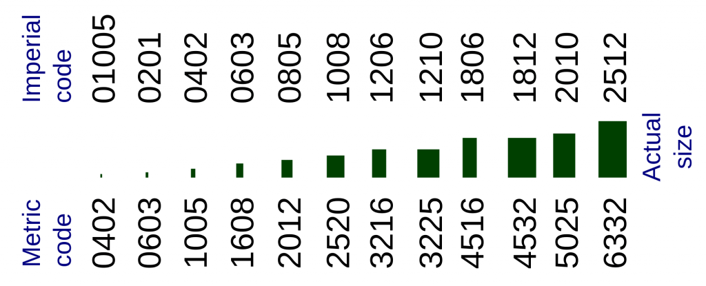
As SMCs are available in a large variety of sizes, designers can select the optimum size of components depending on the application and the available space on the PCB. Rush PCB has the technical expertise to assemble all types and sizes of SMCs effectively.
SMC Packaging
For the manufacturer, packaging and shipping SMCs to the assembler is important, as the components must always remain protected from damage during transit. SMC manufacturers offer various means of packaging, such as tapes, reels, and trays, for transporting components.
Manufacturers place very small SMCs on tapes and wind the tapes onto reels. The tapes are of anti-static material with embossed pockets for the component. To prevent the component from falling off, the tape has a sealing of a thin transparent film on top. The manufacturer offers various standard sizes for the reels, mainly in terms of the number of components on it.
Manufacturers also offer medium and large SMC ICs on tape and reel. However, for large packages such as BGAs, they may use trays, also made of anti-static material, and sealed on top with a thin transparent film.
Manufacturers follow the Electronic Industries Association or EIA standard 481 for packaging. Standardization allows assemblers to place the reels or trays directly in their machines without the need for adjustments. Rush PCB has worldwide contacts with genuine component suppliers for procuring all types of SMCs.
Solder Paste and Stencil Printing
In the SMC assembly process, depositing the solder paste on the printed circuit board is one of the first and an important step. The process aims to accurately deposit the correct amount of solder paste onto each copper pad—if the amount is low, there can be dry solders during reflow. On the other hand, excessive amounts of solder paste deposition may lead to solder bridging.
The most common method assemblers use for depositing solder paste on a PCB is to use a stencil. The stencil has suitable openings through which the assembler forces the solder paste. In practice, the assembler places the stencil on the PCB, aligning them accurately.
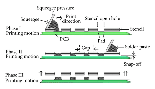
The assembler then places a small quantity of solder paste along one edge of the stencil, and pulls the solder paste over the stencil using a squeegee. This forces the solder paste to pass through the openings in the stencil and deposit on the PCB. The assembler then lifts the stencil leaving the solder paste deposits on the copper pads of the PCB. Rush PCB uses the most optimum type of solder paste and stainless-steel stencils for assembly.
Read About: WHAT IS A SOLDER JOINT?
Pick and Place Machines
Assemblers use pick and place machines to pick the SMC from its tape or tray and place it on the solder paste deposit on the PCB. Use of these machines is the second step in the three-step assembly process of SMCs.
As the name suggests, the basic operation of these machines constitute five steps:
- Locate the SMC on the reel or tray
- Pick up the Component
- Orient the Component Properly
- Locate the Position of the Component on the Board
- Release the Component on the Board
The operator may use a manual method to pick and place SMCs, a semi-automatic machine, or a high-speed, programmable fully automatic machine. The choice depends on several factors such as production volume, time of operation, and precision and accuracy of positioning.
For mounting a few components, an operator can take the manual approach. It requires locating the necessary SMC by sight, picking it up using tweezers, orienting it by sight, locating the placement position on the board, and placing the component on board by releasing it from the tweezers. However, the manual method is not suitable for fine-pitch components that require precision and accuracy while placing, for placing several components, and for placing very small components on the PCB.
The semi- and fully-automatic machines have a pneumatic suction line to aid in picking up the component. Rather than using tweezers, the machines use a head with a pneumatic tube. When the operator positions the head on an SMC, the pneumatic line sucks air out, which causes atmospheric pressure to attach the component to the head. The operator then swivels the head to orient the component and brings it over to the placement position. To place the component, the operator switches the pneumatic line allowing air into the head, and the component drops in place.
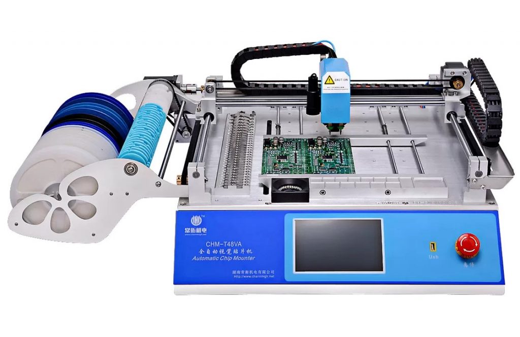
The fully-automatic pick and place machines work much like the semi-automatic types do, except that a programmable computer controls all its actions. Additionally, high-volume machines may have multiple heads all operating independently under computer control. The operator programs the machine to define the five steps. Video cameras attached to the machine provide feedback to the computer to achieve proper precision and accuracy.
The operator places the reels or trays in special attachments available on the machine. When programmed correctly, the machine will advance the tape or tray holding the SMC in step with the head for synchronized pick up and placement.
Using the latest and most accurate pick and place machines, Rush PCB can handle all types of assemblies for rigid, flex, rigid-flex, and HDI boards.
Read About: WHAT IS FIRST ARTICLE ASSEMBLY AND INSPECTION?
Reflow Soldering
This is the final step in the SMC assembly process, before the assembled board goes for inspection and testing. After the pick and place machines have finished placing all components on the board, the operator places the board with its SMCs on the conveyor of a reflow soldering machine.
A reflow soldering machine has several zones inside it, with an arrangement for controlling the temperature inside each zone. The board with its load of SMCs must pass through all the zones before it can come out fully soldered.
Typically, the machine has a few preheat and soak zones to slowly bring the PCB and components closer to the soldering temperature, as they progress through the machine on the conveyor. After the preheat and soak zones, a reflow zone follows, where the temperature melts the solder paste to attach the components to the board. The assembly then passes through a few cooling zones to bring down its temperature gradually.
Several factors contribute to proper soldering by a reflow machine. Major factors are time and temperature. As the size of a reflow machine physically defines the length of its zones, the speed of the conveyor determines how long the board and components will dwell in each zone. The temperature setting of the zone defines how hot the assembly will get while passing through.
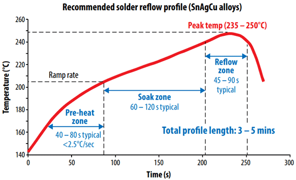
The thermal profile or temperature-time graph for a properly soldered PCB is unique to the assembly, and the operator determines it after a few trials with thermocouples attached to specific places on the PCB.
Conclusion
Rush PCB acts as a one-stop source for all types of PCB manufacturing and full turnkey PCB assembly. Our expert engineers have over twenty years of experience to provide all our customers the quality of work they expect and deserve. Visit our website today, or contact us for a comprehensive quote.


