

Rush PCB recommends using solder resist (the green coating) on the printed circuit boards (PCBs) as a primary protection against oxidation and corrosion. The presence of the solder resist improves the quality of the PCB as it guards against the degradation in its performance and a reduction of its normal operational lifetime of the device.
Furthermore, the solder resist offers several advantages during PCB assembly. These include providing a barrier between the conductive elements of the board and soldered joints, thereby preventing the formation of solder bridges. Therefore, Rush PCB recommends OEMs designing PCBs to understand the process of applying the solder resist and the best practices to follow.
The Solder Resist Process
A PCB fabricator applies solder resist as an important step during PCB manufacturing. Depending on the PCB type, the method of application may include one of the following:
- Screen Printing
- Curtain Coating
- High-Pressure Low Volume (HPLV) Air Spraying
- Electrostatic Spraying
- Inkjet Printing
- Laser Direct Image Printing
Screen Printing
This method is useful for coating both single- and double-sided boards, and Rush PCB recommends it for PCBs using thin cores and flexible substrates. Although screen printing is useful for plugging vias, this method can entrap air.
Curtain Coating
This method is useful for coating only single-sided boards, and therefore, is not suitable for use on PCBs using thin cores and flexible substrates. Curtain coating is not suitable for via plugging, and this method is prone to entrapping air.
HPLV Air Spraying
Although difficult to apply on PCBs using thin cores and flexible substrates, the HPLV air spray method is useful for coating general purpose boards of both single- and double-sided variety.
Electrostatic Spraying
Rush PCB recommends the electrostatic spraying method for coating single- and double-sided PCBs using thin cores and flexible substrates. Although the biggest advantage the electrostatic spraying method is it is not prone to air entrapment, it is not useful for plugging vias.
Special Note
if the design requires via tenting, Rush PCB recommends using processes such as direct or indirect imaging, rather than any of the liquid applications. These include the Ink jet printing and the laser direct image printing. Both are applicable using newer digital printing machines and offer significant process time reductions and cost savings.
Rush PCB can offer any of the above application methods for solder resist printing. For all enquiries regarding solder resist, please contact Rush PCB.
WHY PRINTED CIRCUIT BOARDS NEED OUTGASSING?
Best Practices for Solder Resist
The process of application of solder resist on the PCB is an important issue during manufacturing for the quality and operation of the board. However, it may not always be possible to apply solder resist in certain situations, such as for small components closely spaced or for fine-pitch components such as BGAs. Therefore, OEMs should always consult their Contract Manufacturer to ensure the performance and reliability of their board with the application of solder resist.
Color of Solder Resist
Although green is the most popular color for solder resist, manufacturers do offer other colors as well. Each color has its own advantages:
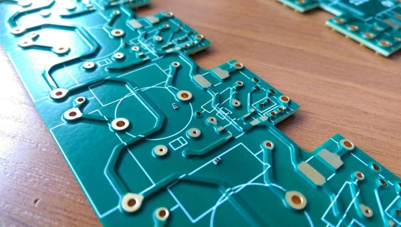
Green—possibility of creating solder resist dams of 0.1 mm width. Wavelength of green light is 550 nm, making green the most visible color to the human eye in daylight and helping tremendously in inspection. The green color makes it easier to distinguish between empty spaces, traces, and copper pads on the PCB.
Red, Blue, Yellow—possibility of creating solder resist dams of 0.12 mm width. These colors provide good contrast and aesthetics for the PCB.
Black and White—possibility of creating solder resist dams of 0.15 mm width. These colors provide the greatest contrast for the PCB. Black color readily absorbs heat, meaning the PCB will require less heat during reflow. White color aids in light reflection and is useful for display boards with LEDs.
So, it is quite important to consider the temperature and chemical resistance of the solder resist before deciding on a specific type. Selecting the right color for the solder resist on your PCB is important from functional as well as aesthetic point of view.
Nevertheless, OEMs should also consider the susceptibility of color shifting during the many chemical treatments and thermal excursions a PCB undergoes during assembly. Rush PCB can offer any color of solder resist for your PCB.
Please contact Rush PCB for all your PCB requirements, including other shades of colors for the solder resist.
HOW CHANNEL OPERATING MARGIN HELPS HIGH-SPEED PCB ANALYSIS
Solder Resist Thickness
The thickness of solder resist primarily depends on the width of copper traces on the PCB. Rush PCB recommends using 0.5 mils of resist over the copper. However, typical thickness of liquid solder resist can vary over the board. Over complex features, specially over the knee of a circuit, the thickness of solder resist may be as thin as 0.4 mils, whereas over empty laminate areas, the thickness may be as much as 1.2 mils.
Industry Standards
PCBs meant for use in regulated sectors such as aerospace, telecommunications, and medicine may require the solder resist to confirm to specific industry standards such as IPC-SM-840D. For this, it is important for the OEM to partner with a good contract manufacturer early in the design process.
So, Rush PCB can help with any requirement of your PCB. Please contact Rush PCB today or visit our website for a quick quote.


