

PCB or Printed Circuit Board designers, targeting high-volume production, are familiar with fiducials. These are copper features, visible through the solder mask openings, typically appearing around the edge of a PCB. Automated imaging equipment uses fiducials to set the board properly against its orientation and angular skew. This helps in the accurate placement and assembly of components on the board. According to Rush PCB Inc., although the above reason is important for the placement of components, designers often place fiducials in other locations as well on the board, such as on panels and stencils, for rotational alignment in computer vision systems.
1. What is a Fiducial?
A fiducials in PCB are a fixed point of reference, primarily for comparison. Designers typically use fiducial marks as surface marks on the board for directional measures for indexing systems.
Automated systems in the electronic assembly industry use fiducial markers as alignment marks for helping indexing systems orient the board in the right direction and skew. The feature allows precise alignment of vision systems when mounting components on the PCB.
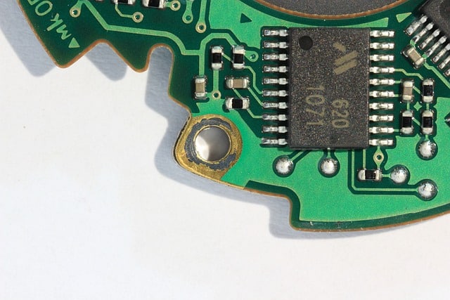
A fiducials in PCB board constitutes three parts:
- A solid copper dot on the top or bottom copper layer
- A solder mask opening
- An optional text label
The copper dot typically has a diameter of 1 mm, while the solder mask opening surrounding it has a diameter of 2-3 mm.
Benchmark Datums
For PCB assembly, automated machines use three benchmark datums:
1. First Datum
This helps mounting machines recognize the location of the PCB. It typically uses a mechanical tooling hole and the X and Y dimensions of the PCB.
2. Second Fiducial Benchmark
This benchmark, also known as global fiducials, helps the machine to recognize the orientation of the board. It also reveals the skew of the PCB if any. This is an important process as even a tiny rotation of the PCB is enough to totally ruin the entire assembly. Fiducial markers ensure the machine orients the rotation of the board to within 0.01 degrees. Accordingly, thereafter, the machine compensates all component placements.
3. Third Fiducial Benchmark
The final benchmark assists mounting machines in compensating for stretches and shrinks in the PCB. All PCBs typically stretch and/or shrink by small amounts during fabrication. This is more evident in larger PCBs, making it essential to identify these variations.
Moreover, reflow of the first side in double-sided SMT assemblies can cause the board to bow, flex, shrink, or stretch. The third fiducial benchmark helps to compensate for that.
2. Placement of Fiducial Markers
1. On the PCB
Designers generally place fiducial markers around the edge of the board, typically near mounting holes in the corners of the board. These global fiducials in PCB allow the mounting machines to examine the orientation of the entire PCB.
Designers also place local fiducial markers around specific components, especially large components like BGAs or groups of very dense components. These markers additionally verify the orientation, shrinkage, or stretching of the board during the processing of these components.
2. On the Panel
Fabricators typically place fiducial markers on the panel, thereby providing orientation measurements for an entire panel while the board proceeds through the fabrication process. They typically place the markers along the panel’s edges, and near the tooling holes, just as they would on a PCB.
Fiducials on the panel are generally the same size as a typical board fiducial. However, individual boards within the panel may have their own arrangement of fiducial markers to provide alignment once they are detached from the panel.
3. On the Stencil
Printed circuit board assembly requires the use of a stencil to dispense solder paste on the PCB pads. The stencil must line up precisely with the pads for the solder paste to appear in the correct areas. Fiducials, as an important part of this process, help with the orientation measurement in aligning the stencil with the copper features on the board.
The stencil typically requires to be accurately aligned with a reference edge or point on the board. Fiducials on the stencil serve the same purpose as in PCBs and panels. However, they only need three global fiducials and no local ones. Stencil manufacturers match the placement of global fiducials on the stencil to the same position as those on the PCB.
Assemblers relying on automated paste dispensing machines do not need to use stencils. These machines use the fiducial markers on the board for orienting and aligning it.
3. Importance of Fiducial Markers
Fiducial markers are essential for pick-and-place machines during PCB assembly. This is because precision is vital for any process that uses automation. Machines must precisely know the exact location of the board and hence, the location of the component they have to place. Fiducial markers help them to orient the board in the right alignment and direction. Assembly machines use high-definition cameras to precisely locate the board with the help of fiducial markers. Therefore, designers must place several fiducial markers on the board in an irreversible pattern.
4. When to Use Fiducial Markers
Fiducial markers are crucial for high volume assembly of components on a board. These markers ensure the correct registration and placement of parts. Although many low-volume assemblers may not use these markers, it is always preferable to use them, whether the assembly is for high or low volumes. However, when placing components manually, fiducial markers are not necessary. Fiducial markers are also not essential when mounting SMCs with large pitches.
5. Basic Principles of Fiducial Marker Design
To obtain the best results during automated machine assembly, PCB designers must get fiducial markers right. Here are some essential guidelines for placing fiducial markers on the board:
The fiducial markers on a non-drilled copper layer must maintain a circular shape. They must also be free from any solder mask.
The marker diameter must optionally be between 1 and 3 mm. The clearance area must preferably be similar to the diameter of the marker.
Use global fiducial markers in sets of three, placing them on the edges of the board. This ensures the best possible accuracy. If space is a limitation, use at least one global marker.
A fiducial marker must maintain a distance of at least 8 mm from the board’s edge. This distance does not include the clearance area of the marker.
There must be at least two local fiducial markers in diagonal positions on the edge plan of the surface mount component.
6. Optimize the Fiducial Marker Design
The designer must consider four factors when designing the fiducial marker. These include:
1. Shape
While modern automated machines can recognize different shapes like the hourglass, diamond, circular, and square, older machines may be able to recognize only circular shapes. Therefore, using circularly shaped markers is a better option for universal recognition.
2. Size
Although fiducial markers can be of various sizes, those measuring between 1 and 3 mm are universally accepted by video cameras and equipment as fiducial markers. It is preferable to have all fiducial markers of the same size on a PCB, with the minimum size of the gap area being twice the radius of the central mark.
3. Material
The fiducial marker must be of the same material as the rest of the board. The marker must be free of solder mask and the silkscreen must not cover it.
4. Clearance
It is vital to maintain proper clearance around the marker. The open space around the marker makes it easier for the camera to locate and recognize it. Preferably, the diameter of the clearance must be at least two times the size of the pad. The shape of the clearance is not crucial, it may be square or circular.
7. Further Considerations
1. Symmetrical Placement
If the fiducial markers appear on both sides of a board and they are in a symmetrical pattern, the assembly machine may not raise an incorrect alarm when the board is turned 180 degrees. Flipping the board by 180 degrees in the reverse direction causes the symmetrical fiducial markers to interchange their positions, thereby deceiving the optical machine.
2. Direct Lighting
Harsh direct lighting from the vision camera above the marker may create bumps, thereby confusing the detector. Uneven solder surfaces often create shadows. The solution is to reduce light levels, use diffused lights, or offset the detection of the fiducial.
3. Placement
Generally, fiducial markers are important enough for designers to place them on both sides of a board that will have SMD components mounted on both sides. Markers on both sides must be clear of solder masks and silk screens.
8. Conclusion
Placing fiducial markers is crucial for most automated machine-mounted and assembled PCBs. The vision system uses these markers for orienting the board and precisely mounting the components. According to Rush PCB Inc., fiducial markers are a crucial aspect of the entire manufacturing process using automated systems for assembly, testing, and packaging.


